
A
Cutting
Waterjet Cutting
Pure-water and abrasive waterjets enable cold cutting without a classic thermal heat-affected zone. Cutting head, pump technology, axis system, and process software form one coordinated system.
Cutting technology →Industrial Waterjet Technology
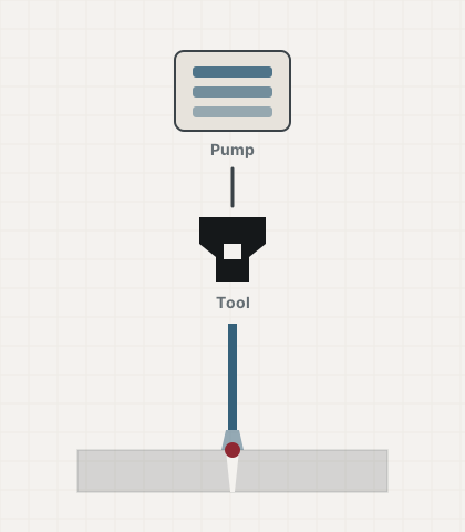
Waterjet systems are used for cutting, cleaning, coating removal, deburring, and specialised post-processing tasks. The right system architecture follows from the process objective, the material or contamination involved, the required throughput, the jetting tool, and the degree of automation.
Breadth of application
A CNC cutting system, a stationary deburring cell, and a mobile ultra-high-pressure unit all run on the same energy carrier, yet differ fundamentally in construction. Selection should therefore start with the process task, not the machine name.
Cutting
Pure-water and abrasive waterjets enable cold cutting without a classic thermal heat-affected zone. Cutting head, pump technology, axis system, and process software form one coordinated system.
Cutting technology →Cleaning & Removal
Pressure, flow rate, nozzle pattern, and traverse speed determine whether contamination is loosened, coatings are stripped, or a surface is removed to a controlled depth.
Cleaning processes →Internal Geometries
Rotating nozzles, lances, hose feeds, and tank-cleaning heads open up geometries where tool guidance and reaction-force control are the central concerns.
Pipe & tank technology →Post-Processing
Enclosed waterjet cabinets are used, among other things, to remove soluble or gel-like support material from PolyJet parts.
Post-processing →System Technology
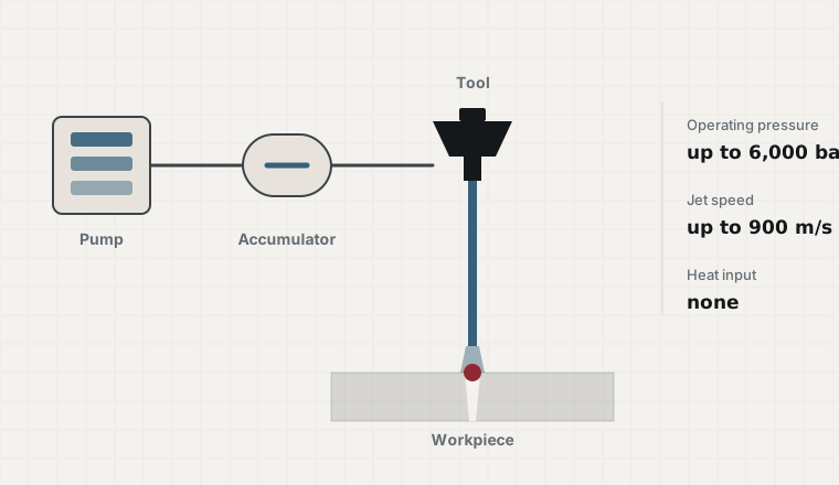
Hydraulic power alone does not describe a suitable waterjet system. Process capability only emerges from how pump, water quality, nozzle, tool motion, safety, and residue management work together.
Technology in detailWater quality, inlet conditions, and filtration must meet the requirements of both the pump and the process.
Operating pressure, flow rate, and drive power are matched to the tool and the machining task.
Nozzle, cutting head, lance, or rotary tool transfer the hydraulic power to the required geometry.
Enclosure, interlocking, water handling, residue, automation, and maintenance access are all part of the system design.
System Concepts
A standardised machine table is only one possible configuration. Depending on the task, waterjet systems range from enclosed processing cells to mobile high-pressure units for work directly on an object.
Contour-following cutting and machining with defined axis kinematics.
↗ 02Cleaning, deburring, and post-processing within a controlled process environment.
↗ 03Flexible tool guidance for complex geometries and recurring process sequences.
↗ 04Power units and water tools for on-site cleaning, maintenance, and material removal.
↗System Selection
A sound technical comparison starts by defining the workpiece or object, its starting condition, the required end condition, cycle time, and ambient conditions. Only after that does it make sense to evaluate pressure, flow rate, nozzle concept, or axis system.
Build a requirements profileDefine the process: cutting, cleaning, coating removal, deburring, material removal, or post-processing.
Set the quality target: cut quality, residual contamination, removal depth, freedom from burrs, or surface condition.
Determine productivity: part count, area throughput, cycle time, and required availability.
Clarify system constraints: space, media, wastewater, noise, access, safety, and service.
Orders of Magnitude
Knowing these reference figures makes it easy to spot, in any quote, whether the rated data and the process task actually match. The derivation is covered under System Technology.
at 1.5–8 l/min. Special systems reach 6,500 bar.
calculated from v = √(2p/ρ), roughly 2.6 times the speed of sound.
DGUV Rule 100-500, chapter 2.36; above 150 N only with additional measures.
pressure-flow product above which the same rule applies, even at moderate pressure.
Calculated values and regulatory references with derivation under System Technology and Standards and Directives.
Tools
Pressure, orifice diameter, and number of orifices together fix the entire hydraulic operating point. The calculator shows flow rate, power, and reaction force for a specific configuration, including the safety-relevant thresholds.
Flow rate, power, reaction force, and pressure-flow product.
↗ CalculatorAbrasive, energy, wear, and disposal per operating hour.
↗ TemplateStructured nine-section request, ready to adapt.
↗ ReferenceTerminology and unit conversion for comparing quotes.
↗